Posts

Showing posts from November, 2008

CW-CCW-RUN-STOP controls

Image
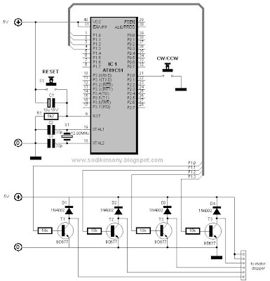
By Sony Sodikin http://www.sodikinsony.blogspot.com/ To run the motor in clockwise rotation, first step is press the CW switch and then press the RUN switch. To stop the motor, press the STOP switch. And so do in counterclockwise rotation, first step is press the CCW switch and then press the RUN switch. When we want to change direction while the motor is running, press the STOP switch, and then select the CW or CCW switch. Hardware Software Software flow chart Source code file in Full Step Mode ;**************************************************************** ;* Title : CW-CCW-RUN-STOP controls * ;* in Full Step Mode * ;* Author : Sony Sodikin * ;* Last updated: 04.03.14 * ;* Target : AT89C51/AT89S51 (AT89CXXXX/AT89SXXXX) * ;**************************************************************** org 0h start: jnb P2.0,start_cw ; cw option jnb p2.1,start_ccw ; ccw option sjmp start start_cw: jnb p2.2,step_cw ; run step cw sjmp start_cw start_ccw: jnb p2.2,step_ccw ; run step ccw sjmp start_cc

Clockwise/counterclockwise direction control with 2 switch (2)

Image
By Sony Sodikin http://www.sodikinsony.blogspot.com/ In this project, the CW switch used to control CW rotation is connected to P2.0 and the CCW switch used to control CCW rotation is connected to P2.1. When the CW switch is pressed, the motor will run in clockwise rotation and when its switch is released (not pressed) the motor still run. When the CCW switch is pressed, the motor will run in counter clockwise rotation and when its switch is released (not pressed) the motor still run. If the motor is running in clockwise rotation, by pressing CCW switch will make the motor runs in counterclockwise rotation. If the motor is running in counterclockwise rotation, by pressing CW switch will make the motor runs in clockwise rotation. Hardware Software Software flow chart Source code file in Full Step Mode ;**************************************************************** ;* Title : CW/CCW direction control with 2 sw (2) * ;*

Clockwise/counterclockwise direction control with 2 switch (1)

Image
By Sony Sodikin http://www.sodikinsony.blogspot.com/ In this project, the CW switch used to control CW rotation is connected to P2.0 and the CCW switch used to control CCW rotation is connected to P2.1. When the CW switch is pressed, the motor will run in clockwise rotation and when its switch is released (not pressed) the motor will stop. When the CCW switch is pressed, the motor will run in counter clockwise rotation and when its switch is released (not pressed) the motor will stop. Hardware Software Software flow chart Source code file in Full Step Mode ;**************************************************************** ;* Title : CW/CCW control with 2 sw (1) * ;* in Full Step Mode * ;* Author : Sony Sodikin * ;* : www.sodikinsony.blogspot.com * ;* Last updated : 04.03.14 * ;* Target : AT89C51/AT89S51 (AT89CXXXX/AT89SXXXX) * ;**************************************************************** org 0h start: jnb P2.0,step_cw jnb p2.1,step_ccw sjmp start step_cw: mov P1,#11111110b ; CW step

Clockwise/counterclockwise direction control with 1 switch

Image
By Sony Sodikin http://www.sodikinsony.blogspot.com/ This is the project for the clockwise rotating or the counter clockwise rotating a unipolar stepper motor. One push button switch connected to P2.0 is used to control clockwise or counter clockwise rotation. Clockwise rotation occurs when P2.0 input is a logic “high” level, and counterclockwise rotation occurs when it is “low”. These mean when switch is pressed the motor will run in clockwise rotation and when switch is released (not pressed) it will run in counter clockwise rotation. Hardware Software Software flow chart Source code file in Full Step Mode ;****************************************************************** ;* Title : Clockwise and counter clockwise control * ;* with 1 switch in full step mode * ;* Author : Sony Sodikin * ;* www.sodikinsony.blogspot.com * ;* Last updated : 04.03.15 * ;* Target : AT89C51/AT89S51 (AT89CXXXX/AT89SXXXX) * ;****************************************************************** org 0h start: jb

Simple program to control Unipolar Stepper Motor

Image
By Sony Sodikin http://www.sodikinsony.blogspot.com/ 1. Full Step mode 1.1 Software flow chart 1.2 Source code file 2. Alternate Full Step mode 2.1 Software flow chart 2.2 Source code file 3. Half Step Mode 3.1 Software flow chart 3.2 Source code file

Unipolar Stepper Motor Controller Using AT89C51/AT89S51 Microcontroller

Image
By Sony Sodikin www.sodikinsony.blogspot.com Introduction Stepper motors are commonly used in accurate motion control. They allow to control any motion with high precision by counting the number of steps applied to the motor. Most of systems controlling stepper motors are embedded systems such as printer, scanner or floppy disk drive. On these pages, I will introduce a control circuit for unipolar stepper motor using AT89C51/AT89S51 microcontroller. System Configuration This note introduces uses the AT89C51/AT89S51 to generate the control signals to the Driver Motor to control unipolar stepper motor. AT89C51/AT89S51 microcontroller output pins cannot directly drive stepper motors. These have to be powered before being applied to the stepper motor. The Driver Motor allows the microcontroller to drive enough current into coils of a stepper motor. Figure 1. System Configuration Hardware AT89C51 microcontroller circuit and driver motor The following schematics shows the AT89C51 microcontro

Driving Unipolar Stepper Motors

Image
By Sony Sodikin http://www.sodikinsony.blogspot.com/ Unipolar Stepper Motor Unipolar stepper motors are characterised by their center-tapped windings. Figure 1. Unipolar Stepper Motors Coils There are three ways to drive unipolar stepper motors (full step, alternate full step or half step), each one has some advantages and disadvantages. Full Step mode Table 1. Full Step Mode Steps Sequence Figure 2. Full Step Mode Steps In full step mode, each successive coil is energized in turn. Full step mode produces smooth rotations and the lowest power consumption of the three modes. Steps are applied in order from one to four. After step four, the sequence is repeated from step one. Applying steps from one to four makes the motor run clockwise, reversing the order of step from four to one will make the motor run counter-clockwise. Figure 3. Full Step Mode Steps Sequence Alternate Full step Mode Table 2. Alternate Full step Mode Steps Sequence Figure 4. Alternate Full step Mode Steps In Alterna