Posts

Showing posts from January, 2009

Red Cyclon Eye

Image
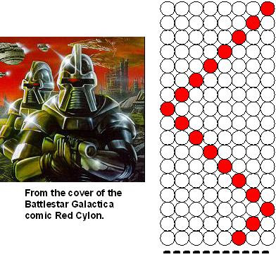
By Sony Sodikin http://www.sodikinsony.blogspot.com/ This project turns on the LEDs connected to port 0 of the microcontroller in sequence, making like a Cylon with the light bouncing back and forth. The data is displayed with about 1/2 second delay between each output pattern. If you don’t know what a Cylon is, try Googling Battlestar Galactica. Circuit Diagram Program Listing /*********************************************************** Title : red cyclon eye Author : Sony Sodikin : http://www.sodikinsony.blogspot.com Date : September,09,2008 Processor : AT89C51 ***********************************************************/ #include void delay(void) { int i; for(i=-32768 ; i } void main(void) { while(1) { int j; for(j = 1; j {P0 ...

Bouncing LED

Image
By Sony Sodikin http://www.sodikinsony.blogspot.com/ This project turns on the LEDs connected to port 0 of the microcontroller in sequence, making the led bouncing back and forth from low speed to high speed. The process is repeated indefinitely with variable delay time. Circuit Diagram Program Listing ;****************************************************************** ;* Title : Bouncing LED * ;* Author : Sony Sodikin * ;* : http://www.sodikinsony.blogspot.com * ;* Date : May 28,2008 * ;* Processor : AT89C51/AT89S51 (AT89CXXXX/AT89SXXXX) * ;****************************************************************** ...

Variation Blinking LED

Image
By Sony Sodikin http://www.sodikinsony.blogspot.com/ This project turns on the LEDs connected to port 0 of the microcontroller in sequence such that first only a led are off, bouncing back and forth, then only a led are on bouncing back and forth. The process is repeated indefinitely with 1 second delay between each output pattern. Circuit Diagram Program Listing /*********************************************************** Title : variation blinking led Author : Sony Sodikin : http://www.sodikinsony.blogspot.com Date : September,09,2008 Processor : AT89C51 ***********************************************************/ #include void delay(void) { int i; for(i=-32768 ; i } void main(void) { while(1) { int j; for(j = 1 ; j {P0 = j; ...

LED Chasing to Right

Image
By Sony Sodikin http://www.sodikinsony.blogspot.com/ This project turns on the LEDs connected to port 0 of the microcontroller in sequence, resulting in a chasing LED effect to right. The data is displayed with about 1 second delay between each output pattern. Circuit Diagram Program Listing /*********************************************************** Title : led chasing to right Author : Sony Sodikin : http://www.sodikinsony.blogspot.com Date : September,09,2008 Processor : AT89C51 ***********************************************************/ #include void delay(void) { int i; for(i=-32768 ; i } void main(void) { while(1) { int j; for(j = 128; j>1 ; j-=j/2) {P0 = ~j; delay(); } } ...

LED Chasing to Left

Image
By Sony Sodikin http://www.sodikinsony.blogspot.com/ This project turns on the LEDs connected to port 0 of the microcontroller in sequence, resulting in a chasing LED effect to left. The data is displayed with about 1 second delay between each output pattern. Circuit Diagram Program Listing /*********************************************************** Title : led chasing to left Author : Sony Sodikin : http://www.sodikinsony.blogspot.com Date : September,09,2008 Processor : AT89C51 ***********************************************************/ #include void delay(void) { int i; for(i=-32768 ; i } void main (void) { while(1) { int j; for(j = 1; j {P0 = ~j; delay(); } } ...

LED Binary Counter 2

Image
By Sony Sodikin http://www.sodikinsony.blogspot.com/ This project counts down in binary and displays the result on eight LEDs connected to port 0 of the microcontroller. The program written in SDCC is required to decrement a value and then output to port 0 of the microcontroller. The data is displayed with about 1 second delay between each output. Circuit Diagram Program Listing /*********************************************************** Title : led binary counter2 Author : Sony Sodikin : http://www.sodikinsony.blogspot.com Date : September,09,2008 Processor : AT89C51 ***********************************************************/ #include void delay(void) { int i; for(i=-32768 ; i } void main(void) { while(1) { int j; for(j = 255 ; j >= 0 ; j--) ...

LED Binary Counter 1

Image
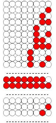
By Sony Sodikin http://www.sodikinsony.blogspot.com/ This project counts up in binary and displays the result on eight LEDs connected to port 0 of the microcontroller. The program written in SDCC is required to increment a value and then output to port 0 of the microcontroller. The data is displayed with about 1 second delay between each output. Circuit Diagram Program Listing /*********************************************************** Title : led binary counter1 Author : Sony Sodikin : http://www.sodikinsony.blogspot.com Date : September,09,2008 Processor : AT89C51 ***********************************************************/ #include void delay(void) { int i; for(i=-32768 ; i } void main(void) { while(1) { int j; for(j = 0 ; j {P0 ...

CW-CCW-RUN-STOP controls with 4 LEDs (2)

Image
By Sony Sodikin http://www.sodikinsony.blogspot.com/ This project schematic is same with CW-CCW-RUN-STOP controls with 4 LEDs project schematic, but at this project, you are possible to change CW/CCW button have pressed as you want before RUN button to be-on (motor isbutton run). Example: You have pressed CW button, but you want By the motor run counter clockwise. So, you just press CCW button and then press RUN . Hardware Software Software flow chart Source code file in Full Step Mode ;**************************************************************** ;* Title : CW-CCW-RUN-STOP controls with 4 LEDs (2)* ;* in Full Step Mode * ;* Author : Sony Sodikin * ;* Last updated : 04. 03.14 * ;* Target : AT89C51/AT89S51 (AT89CXXXX/AT89SXXXX) * ;***********************************...

CW-CCW-RUN-STOP controls with 4 LEDs (1)

Image
By Sony Sodikin www.sodikinsony.blogspot.com This project is same with CW-CCW-RUN-STOP controls project, but it was added four LEDs. LEDs provide visual indication that are used to indicate clockwise, counter clockwise, run, and stop controls. Hardware Software Software flow chart Source code file in Full Step Mode ;**************************************************************** ;* Title : CW-CCW-RUN-STOP controls with 4 LEDs * ;* in Full Step Mode * ;* Author : Sony Sodikin * ;* Last updated: 04.03.14 * ;* Target : AT89C51/AT89S51 (AT89CXXXX/AT89SXXXX) * ;**************************************************************** org 0h start: ...